Equalizer Graphic Equalizer
페이지 정보

본문
MSGEQ7 Interfacing with AVR
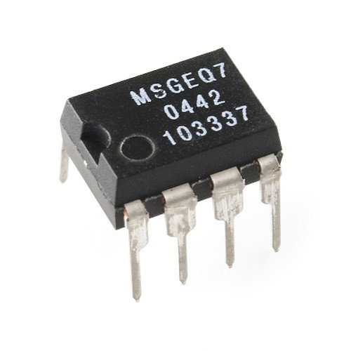
The MSGEQ7 is a 7 band graphic equalizer. What it does is detect the amplitudes of certain frequencies and gives an DC voltage output. The frequencies in question are 63Hz, 160Hz, 400Hz, 1kHz, 2.5kHz, 6.25kHz and 16kHz. Now going through the datasheet of MSGEQ7 we find that it will work with 3.3V or 5V, which is good as our ATMEGA8A is a 5V device. Next we need to build the schematic for the MSGEQ7 IC.
Hardware for MSGEQ7
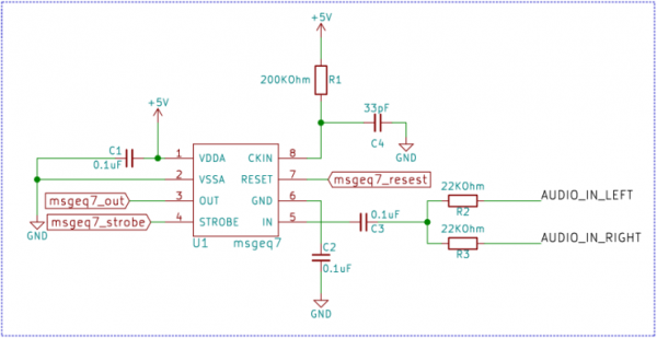
We only need a few parts to get MSGEQ7 working. We need a 200KΩ resistor and a 33pF ceramic capacitor at pin number 8. These two will set the clocking frequency for the MSGEQ7. A 0.1uF capacitor from pin 6 to ground and another from pin 1 to ground for noise protection. A pair of 22KΩ resistors one for each channel in series with a 0.01uF capacitor tied to the input pin number 5.
Fig 1. MSGEQ7 Connection Diagram
Protocol for MSGEQ7
The MSGEQ7 has two control pins RESET and STROBE. After every RESET pulse the multiplexer inside the IC is reset and after every STROBE pulse MSGEQ7 will send the DC voltage corresponding to the frequency on the DC OUT pin. For the First STROBE pulse after RESET the DC OUTPUT voltage will correspond to the first frequency i.e. 63Hz. The next STROBE will correspond with the next frequency i.e. 160Hz and so on. After the 7th STROBE pulse the multiplexer will come back to 63Hz.
Fig 2. Timing Diagram
Schematic
Fig 3. Atmega8 Interfacing With MSGEQ7
Software
main.c
|
1 2 3 4 5 6 7 8 9 10 11 12 13 14 15 16 17 18 19 20 21 22 23 24 25 26 27 28 29 30 31 32 33 34 35 36 37 38 39 40 41 42 43 44 45 46 47 48 49 50 51 52 53 54 55 56 57 58 59 60 61 62 63 64 65 66 67 68 69 70 71 72 73 74 75 76 77 |
|
msgeq7.h
|
1 2 3 4 5 6 7 8 9 10 11 12 13 14 15 16 |
|
msgeq7.c
|
1 2 3 4 5 6 7 8 9 10 11 12 13 14 15 16 17 18 19 20 21 22 23 24 25 26 27 28 29 30 |
|
첨부파일
-
Graphic Equalizer.zip (383.0K)
585회 다운로드 | DATE : 2019-10-21 17:52:45
댓글목록
등록된 댓글이 없습니다.

