전기/전자

IT HUB를 찾아주셔서 감사합니다.

Equalizer Graphic Equalizer

페이지 정보

profile_image
작성자 하나를하더라도최선을
댓글 0건 조회 6,418회 작성일 19-10-21 17:52

본문

268ef5b6e5d1b1afec286fa1b84e1169_1571647916_5146.png
268ef5b6e5d1b1afec286fa1b84e1169_1571647916_6238.jpg


MSGEQ7 Interfacing with AVR

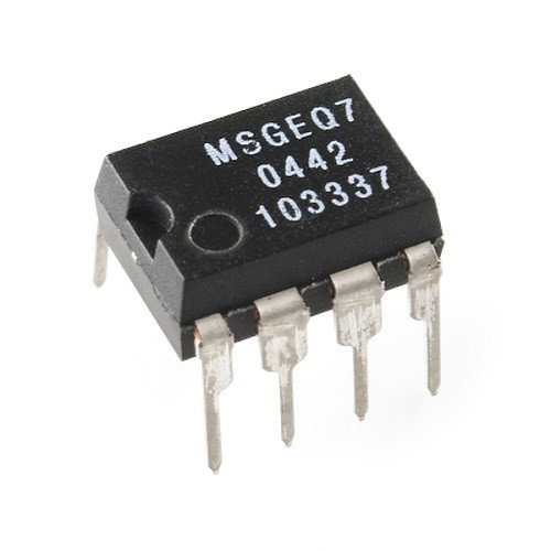
The MSGEQ7 is a 7 band graphic equalizer. What it does is detect the amplitudes of certain frequencies and gives an DC voltage output. The frequencies in question are 63Hz, 160Hz, 400Hz, 1kHz, 2.5kHz, 6.25kHz and 16kHz. Now going through the datasheet of MSGEQ7 we find that it will work with 3.3V or 5V, which is good as our ATMEGA8A is a 5V device. Next we need to build the schematic for the MSGEQ7 IC.

Hardware for MSGEQ7

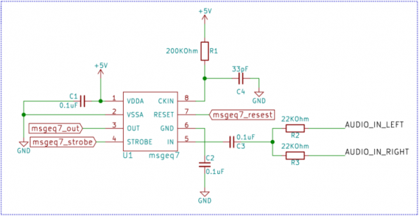
We only need a few parts to get MSGEQ7 working. We need a 200KΩ resistor and a 33pF ceramic capacitor at pin number 8. These two will set the clocking frequency for the MSGEQ7. A 0.1uF capacitor from pin 6 to ground and another from pin 1 to ground for noise protection. A pair of 22KΩ resistors one for each channel in series with a 0.01uF capacitor tied to the input pin number 5.

Fig 1. MSGEQ7 Connection Diagram

Protocol for MSGEQ7

The MSGEQ7 has two control pins RESET and STROBE. After every RESET pulse the multiplexer inside the IC is reset and after every STROBE pulse MSGEQ7 will send the DC voltage corresponding to the frequency on the DC OUT pin. For the First STROBE pulse after RESET the DC OUTPUT voltage will correspond to the first frequency i.e. 63Hz. The next STROBE will correspond with the next frequency i.e. 160Hz and so on. After the 7th STROBE pulse the multiplexer will come back to 63Hz.

Fig 2. Timing Diagram

Schematic

Fig 3. Atmega8 Interfacing With MSGEQ7

Software

main.c

1

2

3

4

5

6

7

8

9

10

11

12

13

14

15

16

17

18

19

20

21

22

23

24

25

26

27

28

29

30

31

32

33

34

35

36

37

38

39

40

41

42

43

44

45

46

47

48

49

50

51

52

53

54

55

56

57

58

59

60

61

62

63

64

65

66

67

68

69

70

71

72

73

74

75

76

77

#include <avr/io.h>


#include "msgeq7.h"


//Three LEDSs connected to PWM Outputs

#define SET_LED1_BRIGHTNESS(x) (OCR2=x)

#define SET_LED2_BRIGHTNESS(x) (OCR1BL=x)

#define SET_LED3_BRIGHTNESS(x) (OCR1AL=x)


void IO_init(void);

void TIMER_init(void);

void ADC_init(void);

unsigned char ReadAnalog(void);


int main(void)

{

unsigned char result[7];

IO_init();

TIMER_init();

ADC_init();

/* Replace with your application code */

msgeq7_reset();

while (1)

{

msgeq7_getValues((char *)&result);

SET_LED1_BRIGHTNESS(result[0]);

SET_LED2_BRIGHTNESS(result[3]);

SET_LED3_BRIGHTNESS(result[6]);

}

}


void IO_init(void){

//PORTB as output

DDRB=0XFF;


//PORTB as current source

PORTB=0XFF;


//PORTD pins D7 and D4 as output

DDRD|=(1<<DDRD7)|(1<<DDRD4);

}


void TIMER_init(void){

//timer2 in fast PWM mode and inverting output on OCR2

TCCR2|=(1<<COM21)|(1<<COM20)|(1<<WGM21)|(1<<WGM20)|(1<<CS20);


//tiemr1 in fast PWM mode and inverting output on OCR1A and OCR1B

TCCR1A|=((1<<COM1A0)|(1<<COM1A1)|(1<<WGM10)|(1<<COM1B0)|(1<<COM1B1));

TCCR1B|=(1<<WGM12)|(1<<CS10);

}


void ADC_init(){

//Select internal referance and Channel 0

ADMUX|=(1<<REFS0)|(1<<REFS1);


//Enable ADC and ADC frequency=clock frequency/4

ADCSRA|=(1<<ADEN)|(1<<ADPS1);

}


unsigned char ReadAnalog(void){

//interger to store 10-bit ADC value

unsigned int result=0;


//start conversion

ADCSRA|=(1<<ADSC);


//wait till converion is done

while(ADCSRA&(1<<ADSC));


//read result

result=ADCW;


//return 10-bit value mapped to 8-bit value i.e 1024/4=256

return (unsigned char)(result/4);

}

msgeq7.h

1

2

3

4

5

6

7

8

9

10

11

12

13

14

15

16

#ifndef INCFILE1_H_

#define INCFILE1_H_


#define STROBE_PORT PORTD

#define STROBE_PIN PORTD4


#define RESET_PORT PORTD

#define RESET_PIN PORTD7


void msgeq7_reset(void);

void msgeq7_getValues(char * const);


#endif /* INCFILE1_H_ */

msgeq7.c

1

2

3

4

5

6

7

8

9

10

11

12

13

14

15

16

17

18

19

20

21

22

23

24

25

26

27

28

29

30

#define F_CPU 16000000

#include <avr/io.h>

#include <util/delay.h>

#include "msgeq7.h"

unsigned char ReadAnalog(void);


void msgeq7_reset(){

STROBE_PORT|=(1 << STROBE_PIN); //make sure that STORBE pin is high before RESET

_delay_us(100);


RESET_PORT|=(1 << RESET_PIN);

_delay_us(100);


RESET_PORT &= ~(1 << RESET_PIN);

_delay_us(100);


}

void msgeq7_getValues(char * const result){

unsigned char i=0;

for(i=0;i<7;i++){

STROBE_PORT&= ~(1 << STROBE_PIN);

_delay_us(100);

result[i]=ReadAnalog();


if(result[i]<60)

result[i]=0;

STROBE_PORT|=(1 << STROBE_PIN);

_delay_us(100);

}

}


추천0 비추천0

첨부파일

댓글목록

등록된 댓글이 없습니다.

Total 6건 1 페이지
  • RSS
전기/전자 목록
번호 제목 글쓴이 조회 추천 비추천 날짜
6 MCU 하나를하더라도최선을 1268 0 0 07-20
5 MCU 하나를하더라도최선을 1202 0 0 07-12
4 MCU 하나를하더라도최선을 1048 0 0 07-10
3 hardware 하나를하더라도최선을 4481 0 0 09-17
2 hardware 하나를하더라도최선을 6071 0 0 09-17
1 회로도 하나를하더라도최선을 10786 0 0 12-17
0 회로도 하나를하더라도최선을 10514 0 0 12-10
열람중 Equalizer 하나를하더라도최선을 6419 0 0 10-21

검색